

How To Find Initial Voltage Across A Capacitor
Resistors and Capacitors in Serial
An RC circuit has a resistor and a capacitor and when connected to a DC voltage source, and the capacitor is charged exponentially in time.
Learning Objectives
Describe the components and office of an RC circut, noting especially the fourth dimension-dependence of the capacitor'due south accuse
Key Takeaways
Central Points
- In an RC excursion connected to a DC voltage source, the electric current decreases from its initial value of I0=emf/R to zippo as the voltage on the capacitor reaches the aforementioned value as the emf.
- In an RC circuit connected to a DC voltage source, voltage on the capacitor is initially zip and rises rapidly at commencement since the initial current is a maximum: [latex]\text{V}(\text{t})= \text{emf}(1-\text{e}^{\text{t}/\text{RC}})[/latex].
- The time constant τ for an RC excursion is defined to be RC. It's unit is in seconds and shows how quickly the circuit charges or discharges.
Key Terms
- DC: Straight current; the unidirectional flow of electric charge.
- capacitor: An electronic component capable of storing an electric charge, especially 1 consisting of two conductors separated by a dielectric.
- differential equation: An equation involving the derivatives of a function.
An RC circuit is i containing a resistor R and a capacitor C. The capacitor is an electrical component that houses electric charge. In this Cantlet, we will study how a serial RC circuit behaves when connected to a DC voltage source. (In subsequent Atoms, we will study its AC behavior. )
Charging
Fig i shows a elementary RC circuit that employs a DC voltage source. The capacitor is initially uncharged. As before long as the switch is closed, electric current flows to and from the initially uncharged capacitor. As charge increases on the capacitor plates, there is increasing opposition to the flow of accuse past the repulsion of similar charges on each plate.
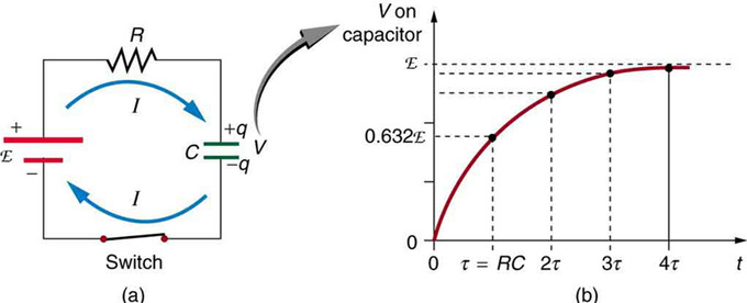
Charging an RC Circuit: (a) An RC circuit with an initially uncharged capacitor. Current flows in the management shown every bit before long as the switch is closed. Mutual repulsion of like charges in the capacitor progressively slows the menstruation equally the capacitor is charged, stopping the current when the capacitor is fully charged and Q=C⋅emf. (b) A graph of voltage across the capacitor versus time, with the switch endmost at fourth dimension t=0. (Note that in the two parts of the figure, the capital script Eastward stands for emf, q stands for the accuse stored on the capacitor, and τ is the RC time constant. )
In terms of voltage, across the capacitor voltage is given by Vc=Q/C, where Q is the amount of charge stored on each plate and C is the capacitance. This voltage opposes the battery, growing from naught to the maximum emf when fully charged. Thus, the current decreases from its initial value of I0=emf/R to zero equally the voltage on the capacitor reaches the aforementioned value as the emf. When there is no electric current, at that place is no IR drop, and then the voltage on the capacitor must and then equal the emf of the voltage source.
Initially, voltage on the capacitor is nada and rises rapidly at outset since the initial electric current is a maximum. Fig 1 (b) shows a graph of capacitor voltage versus time (t) starting when the switch is closed at t=0. The voltage approaches emf asymptotically since the closer it gets to emf the less current flows. The equation for voltage versus time when charging a capacitor C through a resistor R, is:
[latex]\text{V}(\text{t})= \text{emf}(1-\text{e}^{\text{t}/\text{RC}})[/latex],
where V(t) is the voltage beyond the capacitor and emf is equal to the emf of the DC voltage source. (The exact form can be derived past solving a linear differential equation describing the RC circuit, but this is slightly beyond the scope of this Cantlet. ) Note that the unit of RC is second. Nosotros define the fourth dimension constant τ for an RC excursion as [latex]\tau = \text{RC}[/latex]. τ shows how quickly the circuit charges or discharges.
Discharging
Discharging a capacitor through a resistor gain in a similar fashion, as illustrates. Initially, the current is I0=V0/R, driven past the initial voltage Five0 on the capacitor. As the voltage decreases, the electric current and hence the charge per unit of belch decreases, implying another exponential formula for V. Using calculus, the voltage V on a capacitor C existence discharged through a resistor R is found to exist
[latex]\text{V}(\text{t}) = \text{Five}_0 \text{e}^{-\text{t}/\text{RC}}[/latex].
Impedance
Impedance is the measure out of the opposition that a circuit presents to the passage of a electric current when a voltage is applied.
Learning Objectives
Express the relationship between the impedance, the resistance, and the capacitance of a series RC excursion in a grade of equation
Cardinal Takeaways
Key Points
- The advantage of assuming that sources take complex exponential form is that all voltages and currents in the circuit are too complex exponentials, having the same frequency as the source.
- The major upshot of assuming complex exponential voltage and currents is that the ratio (Z = V/I) for each element does not depend on time, but does depend on source frequency.
- For a series RC excursion, the impedance is given as [latex]\text{Z} = \sqrt{\text{R}^2+(\frac{1}{\omega \text{C}})^2}[/latex].
Key Terms
- impedance: A mensurate of the opposition to the flow of an alternating current in a circuit; the aggregation of its resistance, inductive and capacitive reactance. Represented by the symbol Z.
- Ac: Alternating current.
- capacitor: An electronic component capable of storing an electrical charge, particularly ane consisting of two conductors separated by a dielectric.
- resistor: An electric component that transmits electric current in straight proportion to the voltage across it.
Rather than solving the differential equation relating to circuits that incorporate resistors and capacitors, nosotros tin imagine all sources in the circuit are complex exponentials having the same frequency. This technique is useful in solving issues in which phase relationship is of import. The phase of the complex impedance is the phase shift past which the current is alee of the voltage.
Complex Analysis
For an RC excursion in, the Air conditioning source driving the circuit is given equally:

Serial RC Circuit: Series RC circuit.
[latex]\text{five}_{\text{in}}(\text{t}) = \text{Five} \text{east}^{\text{j} \omega \text{t}}[/latex],
where V is the amplitude of the Air-conditioning voltage, j is the imaginary unit (jii=-1), and [latex]\omega[/latex] is the athwart frequency of the AC source. Two things to note:
- We apply lower instance alphabets for voltages and sources to represent that they are alternating (i.due east., nosotros use vin(t) instead of 5in(t)).
- The imaginary unit is given the symbol "j", non the usual "i". "i" is reserved for alternating currents.
Circuitous Impedance
The advantage of bold sources take this grade is that all voltages and currents in the excursion are too complex exponentials (having the same frequency as the source). To capeesh the reason for this, we tin investigate how each circuit element behaves when either the voltage or current is a circuitous exponential. For the resistor, [latex]\text{v} = \text{Ri}[/latex]. From our voltage given above, [latex]\text{i} = \frac{\text{V}}{\text{R}} \text{e}^{\text{j} \omega \text{t}}[/latex]. Thus the resistor's voltage is a complex, equally is the current with an aamplitude [latex]\text{I} = \frac{\text{V}}{\text{R}}[/latex]. For a capacitor, [latex]\text{i} = \text{C} \frac{\text{dv}}{\text{dt}}[/latex]. Letting the voltage be a complex exponential we have [latex]\text{i} = \text{j} \omega \text{CV} \text{e}^{\text{j} \omega \text{t}}[/latex]. The amplitude of this complex exponential is [latex]\text{I} = \text{j} \omega \text{CV}[/latex].
The major event of assuming circuitous exponential voltage and currents is that the ratio [latex]\text{Z} = \frac{\text{V}}{\text{I}}[/latex] for rather than depending on time each chemical element depends on source frequency. This quantity is known as the chemical element's (circuitous) impedance. The magnitude of the complex impedance is the ratio of the voltage amplitude to the current amplitude. Merely like resistance in DC cases, impedance is the mensurate of the opposition that a circuit presents to the passage of a current when a voltage is practical. The impedance of a resistor is R, while that of a capacitor (C) is [latex]\frac{1}{\text{j} \omega \text{C}}[/latex]. In the case of the circuit in, to notice the circuitous impedance of the RC circuit, nosotros add together the impedance of the two components, only as with ii resistors in series: [latex]\text{Z} = \text{R} + \frac{ one}{\text{j} \omega \text{C}}[/latex].
Finding Existent Currents and Voltages
Since [latex]\text{due east}^{\text{j}\omega \text{t}} = \text{cos}(\omega \text{t}) + \text{j} \text{sin}(\omega \text{t})[/latex], to find the existent currents and voltages nosotros simply need to accept the real role of the i(t) and v(t). The (real value) impedance is the existent part of the complex impedance Z. For a series RC circuit, we get [latex]\text{Z} = \sqrt{\text{R}^2+(\frac{1}{\omega \text{C}})^two}[/latex]. We encounter that the aamplitude of the current will be [latex]\text{V}/\text{Z} = \frac{\text{Five}}{\sqrt{\text{R}^2+(\frac{1}{\omega \text{C}})^2}}[/latex].
Stage Bending and Power Factor
In a series RC circuit connected to an Ac voltage source, voltage and current maintain a phase difference.
Learning Objectives
Compare the currents in the resistor and capacitor in a series RC circuit connected to an Air-conditioning voltage source
Key Takeaways
Key Points
- In a serial RC circuit connected to an AC voltage source, the currents in the resistor and capacitor are equal and in phase.
- In a series RC circuit connected to an Ac voltage source, the total voltage should be equal to the sum of voltages on the resistor and capacitor.
- In a serial RC circuit continued to an Air-conditioning voltage source, voltage and current have a phase difference of [latex]\phi[/latex], where [latex]cos\phi = \frac{\text{R}}{\sqrt{\text{R}^2+(\frac{1}{\omega \text{C}})^2}}[/latex]. cosϕ is called the power factor.
Key Terms
- impedance: A measure of the opposition to the catamenia of an alternating current in a circuit; the aggregation of its resistance, inductive and capacitive reactance. Represented by the symbol Z.
- alternating current: (Air conditioning)—An electric current in which the direction of menstruum of the electrons reverses periodically having an average of zero, with positive and negative values (with a frequency of l Hz in Europe, 60 Hz in the US, 400 Hz for airport lighting, and some others); especially such a electric current produced past a rotating generator or alternator.
- rms: Root mean square: a statistical measure of the magnitude of a varying quantity.
Phase Bending
Impedance is an Air conditioning (alternating current) analogue to resistance in a DC excursion. As we studied in a previously Atom ("Impedance"), current, voltage and impedance in an RC circuit are related past an AC version of Ohm 's law: [latex]\text{I} = \frac{\text{V}}{\text{Z}}[/latex], where I and Five are summit current and height voltage respectively, and Z is the impedance of the circuit.
In a series RC circuit connected to an Air-conditioning voltage source every bit shown in, conservation of charge requires current be the same in each part of the circuit at all times. Therefore nosotros can say: the currents in the resistor and capacitor are equal and in phase. (We will represent instantaneous electric current as i(t). )
Serial RC Circuit: Series RC circuit.
On the other mitt, because the total voltage should be equal to the sum of voltages on the resistor and capacitor, so we have:
[latex]\brainstorm{align} \text{v}(\text{t})& = \text{v}_\text{R}(\text{t})+\text{v}_\text{C}(\text{t}) \\ &= \text{i}(\text{t})\text{R} + \text{i}(\text{t})\frac{1}{\text{j} \omega \text{C}} \\ &= \text{i}(\text{t}) (\text{R}+\frac{ane}{\text{j}\omega \text{C}}) \terminate{align}[/latex],
where [latex]\omega[/latex] is the athwart frequency of the Air-conditioning voltage source and j is the imaginary unit of measurement; j2=-i. Since the circuitous number [latex]\text{Z} = \text{R}+\frac{1}{\text{j}\omega \text{C}} = \sqrt{\text{R}^ii+(\frac{1}{\omega \text{C}})^2} \text{e}^{\text{j}\phi}[/latex] has a phase angle [latex]\phi[/latex] that satisfies [latex]\text{cos}\phi = \frac{\text{R}}{\sqrt{\text{R}^2+(\frac{1}{\omega \text{C}})^2}}[/latex],
we notice that voltage [latex]\text{v}(\text{t})[/latex] and current [latex]\text{i}(\text{t})[/latex] has a phase deviation of [latex]\phi[/latex].
For R=0, [latex]\phi = 90^{\circ}[/latex]. Every bit learned from the preceding series of Atoms—the voltage beyond the capacitor FiveC follows the current by one-quaternary of a bicycle (or 90º).
Power Factor
Because voltage and current are out of phase, power dissipated past the excursion is not equal to: (peak voltage) times (peak current). The fact that source voltage and current are out of phase affects the power delivered to the circuit. It can be shown that the average power is IrmsVrmscosϕ, where Irms and Fiverms are the root hateful square (rms) averages of the electric current and voltage, respectively. For this reason, cosϕ is called the power factor, which can range from 0 to ane.

Source: https://courses.lumenlearning.com/boundless-physics/chapter/rc-circuits/
Posted by: ryanlesse1976.blogspot.com
0 Response to "How To Find Initial Voltage Across A Capacitor"
Post a Comment